Project Details
Client : University of Botswana
Cost of Works (Estimate) : P250, 000,000.00
Date of Completion : 2011

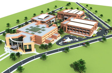
Figure 1: Faculty of Engineering Building Model
Project Description
This development comprised of offices, teaching rooms and laboratories for the Faculty of Engineering and Technology at the University of Botswana. The mechanical services provided were design and construction supervision of installation of
- Heating, Ventilation and Air Conditioning systems
- Fire Protection
- Wet Services
- Compressed Air System
| Figure 1: Faculty of Engineering Building Model |
The building consist of 4 wings of Blocks named; A&P, MCME, EMC and Admin.
The Admin Block consists of Classrooms, Computer Labs and office spaces for all FET staff. A & P consist of classrooms and design rooms. A & P and Admin Blocks are serviced with chilled water cooling system, fresh air supply and Ventilation in male and female change rooms/toilets.
MCME and EMC consist mainly of courses or modules dedicated workshops. The workshops are serviced with chilled water cooling system, Fresh Air supply, Ventilation in toilets and Compressed air supply to some workshop rooms.
The Faculty is serviced with Fire Hose Reels and Fire Extinguishers for fire protection.
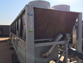
Figure 2: Chiller Plant Room at Roof Slab
Chilled Water Plant and Associated Distribution Pipework
We provide below a brief overview of the proposed mechanical services installation for the above
- Generally, space cooling is provided by chilled water. The central chilled water generating plant comprise of; 4No. air-cooled liquid chillers, primary chilled water circulating pumps, secondary chilled water circulating pumps, air separators, a system of chilled water distribution pipework and valves and fittings.
- liquid chillers each of 1100kW cooling capacity are located above the EMI Building roof slab to serve the EMI Workshop and the Administration Building.
- Another 2No. liquid chillers each of 600kW cooling capacity are located above the MCME Workshop roof slab to serve the MCME Workshop and the Architecture and
- Supply of chilled water to other buildings by means of chilled water pipes running under corridor roofing and then rising into service ducts to feed respective buildings. This was to preserve architectural design by keeping mechanical services installations aesthetic with Architectural designs.
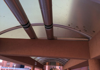
Figure 3: Chilled Water distribution Pipes running under corridor roof and with similar painting of the roof.
BMS SYSTEM
- The BMS system shall be able to read control, monitor, and display chilled water flow and return for all Primary and Secondary Circuits for all chillers distribution network for Building Blocks.
- In BMS Monitoring System alarms shall be displayed on screen for Liquid Chiller Trips, Primary and Secondary circulating Pumps trips, Liquid Chiller High Flow temperatures.
- All alarms will appear as a priority “Pop Up” on the BMS Monitoring Screen. The alarms will flash until there are acknowledged.
- The BMS system have facility to keep a history of all the system faults, and to maintain a database of maintenance information for each system, such as Air Filter Replacement, Chilled Water Pump of Pump Motor Replacement, Compressor Replacement, 3-way Valve Replacement, etc.
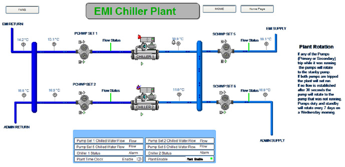
Figure 4: BMS System display showing the status of the chiller system located at EMI Building Roof Slab.
Keywords
- UB
- FET
- Faculty of Engineering Technology
- BMS
- Chilled Water System
- HVAC